Understanding Cut Geometry Specifications for CNC Machining
Before diving into measurement, it’s important to understand the key terms in cut geometry specifications, as they directly impact the quality and functionality of your CNC parts.
Minimum hole size refers to the smallest diameter that can be accurately cut or drilled. This varies depending on the cutting method—laser cutting typically has tighter tolerances compared to waterjet or CNC routing. Exceeding the minimum size can cause poor hole quality or incomplete cuts.
Bridge width is the narrowest strip of material left between two cut features or openings. Maintaining proper bridge width is crucial to prevent part distortion and maintain structural integrity during cutting.
Hole to edge distance defines the minimum space between a hole and the edge of the material. Too close, and the material risks cracking or warping at the cut edges.
Flange length is the length of a bent or extended section in sheet metal parts, often critical for assembly and fit.
These geometry specifications matter because each CNC process—laser cutting, waterjet cutting, and CNC routing—has different requirements for accuracy, material interaction, and machine capability. Adhering to these specs ensures clean cuts, reduces waste, and prevents costly rework.
Industry standards commonly reference hole sizes and material thickness to guide designers and machinists. For example, thicker materials require larger minimum hole sizes or wider bridge widths to compensate for heat dispersion or machine tool limitations.
Understanding these terms and why they matter will help you prepare accurate designs that meet CNC service providers’ requirements, such as those from HYCNC. This foundation supports precise measurement in QCAD and alignment with professional manufacturing standards.
Getting Started with QCAD for Measurement
Before you start measuring cut geometry specifications with QCAD, you need to get the software ready. Here’s a simple way to download and set up QCAD so you can begin.
Downloading and Setting Up QCAD
- Visit the official QCAD website and download the latest version compatible with your system (Windows, macOS, or Linux).
- Follow the installation prompts; it usually takes just a few minutes.
- Once installed, open QCAD and familiarize yourself with the interface—knowing where the tools are will speed up your measuring process.
Importing Your Design File
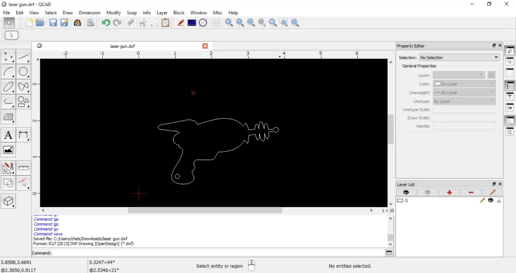
- To start measuring, you’ll need your design file in a QCAD-friendly format like DXF or DWG.
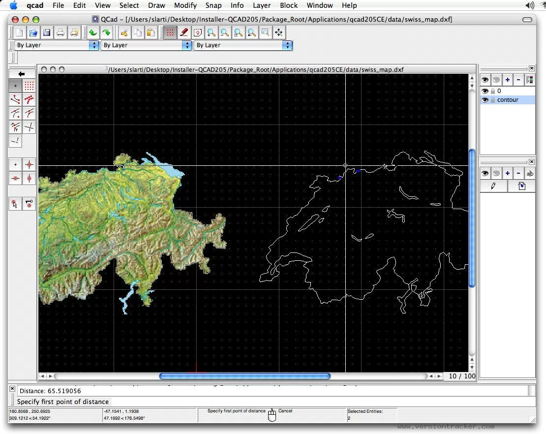
- Click on “File” then “Open,” and choose your design file.
- After loading, zoom in on the areas you want to measure, making sure your parts and layers are visible.
- Double-check that your drawing units (inches or millimeters) match the specifications you need to measure against.
Getting your file imported correctly ensures your QCAD measurement tools work accurately, especially when checking key aspects like holes, bridge widths, or flange lengths for CNC machining.
For more design preparation tips, check out our guide on Preflight Your Designs Using QCAD.
Step by Step Guide to Measuring Cut Geometry in QCAD
When it comes to checking your CNC cut geometry, QCAD makes the process straightforward with its built-in measurement tools. Here’s how you can measure key features like holes, cutouts, bridge widths, and edge distances.
Using QCAD Measurement Tools
- Open your design in QCAD.
- Go to the Measure menu on the toolbar. Here you’ll find options like Distance, Diameter, Angle, and more.
- Select the tool based on what you need to measure. For most cut geometry specs, Distance and Diameter are the ones you’ll use the most.
Measuring Specific Features
-
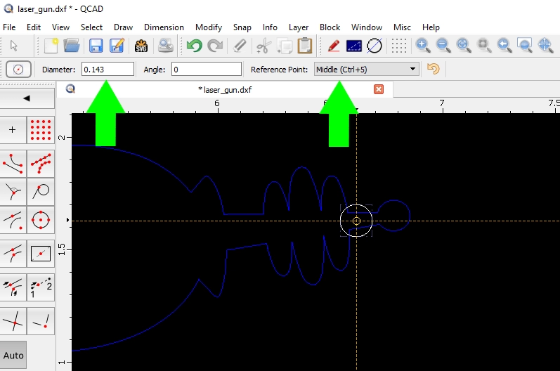
Holes and Cutouts
Use the Diameter tool to click on the circular edges of a hole or cutout. QCAD will show you the exact diameter, helping you verify your minimum hole size.
-
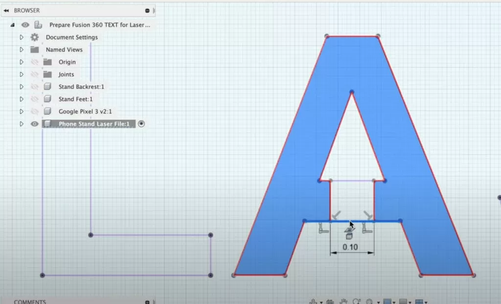
Bridge Width and Edge Distances
For measuring the width of bridges or how close a cut is to the edge, use the Distance tool. Click the two points defining the width or distance, and the tool calculates the exact number for you.
-
Offset with Distance Tool
This is handy when you want to check clearances or maintain minimum distances between features. You can use the Offset function to create a parallel line or shape at a set distance, ensuring your design meets specs like hole to edge distance or flange length.
By following these steps in QCAD, you’ll easily confirm that your design matches CNC machining and laser cutting requirements before sending your file to HYCNC.
Verifying Against HYCNC Specifications
Once you’ve measured your cut geometry using QCAD, it’s important to double-check your dimensions against HYCNC specifications. HYCNC has clear guidelines on minimum hole sizes, bridge widths, hole-to-edge distances, and flange lengths to ensure your design is CNC-ready and won’t cause issues during machining.
Here’s how to verify your design with HYCNC specs:
- Check minimum hole size: HYCNC usually requires holes to be above a certain diameter based on material thickness. Make sure your measurements meet or exceed this to avoid drilling or cutting problems.
- Confirm bridge width: Bridges need to be thick enough to hold the part securely during cutting. Measure with QCAD and compare with HYCNC’s recommended minimums.
- Verify hole-to-edge distance: Holes placed too close to edges can weaken your part or cause defects. Use the distance tool in QCAD to measure and ensure your design follows HYCNC’s guidelines.
- Review flange lengths and other features: Make sure flanges and other key geometry elements match HYCNC’s specs to maintain part strength and compatibility.
By aligning your QCAD measurements with HYCNC’s CNC cut geometry requirements, you reduce the risk of remakes, delays, and added costs. Always keep HYCNC’s design guidelines handy during your layout and measurement process for a smooth transition from design to production.
Common Mistakes to Avoid When Measuring in QCAD
When working with QCAD to check your cut geometry specs, it’s easy to slip up. Here are some common mistakes to watch out for:
-
Not Zooming In Close Enough
Small features like minimum hole sizes or narrow bridge widths can be missed if you don’t zoom in properly. Always get a close-up view before measuring.
-
Using the Wrong Measurement Tool
QCAD has several tools—distance, radius, angle, etc. Using the wrong tool can give you inaccurate readings. For cut geometry, stick to the distance and dimension tools to measure holes, edges, and bridges precisely.
-
Ignoring Snap Settings
Snap options help your cursor lock onto key points like endpoints or midpoints. If snaps are off or set incorrectly, your measurements won’t line up accurately with the design.
-
Measuring from the Wrong Reference Point
Check if you’re measuring from the actual edge, center, or midpoint, depending on what spec you need. For example, hole-to-edge distance means measuring from a hole’s center to the material edge.
-
Forgetting to Check Units
Make sure your QCAD document units (inches or millimeters) match the specs you’re working with. A mismatch here can cause costly errors in CNC cutting.
-
Overlooking Material Thickness Impact
Some specs depend on the material thickness, like minimum hole size or flange length. Don’t just measure geometry; confirm specs align with your material.
Avoiding these mistakes helps ensure your CNC cut geometry measurements in QCAD are accurate and ready to meet HYCNC or other industry guidelines.
Exporting and Submitting Your Design to HYCNC
Once you’ve measured and double-checked your cut geometry specs in QCAD, it’s time to export your file for HYCNC. Make sure your design matches their guidelines before submission to avoid delays.
Here’s how to prepare and send your design:
-
Export as a compatible file type: HYCNC usually accepts DXF or DWG files. In QCAD, go to File > Export and choose DXF to keep your 2D design intact.
-
Check layers and units: Confirm that all layers needed for cutting are visible and properly named. Also, verify that your drawing units match HYCNC’s requirements (usually inches or millimeters).
-
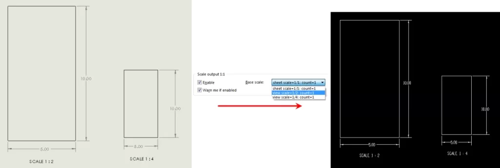
Review scale and dimensions: Ensure your design is at a 1:1 scale, so measurements are accurate for CNC machining.
-
Clean up your drawing: Remove any unnecessary elements like construction lines or notes that won’t be used in the cutting process.
-
Submit through HYCNC’s platform: Upload your exported file via their website or send it by email as per their submission instructions.
By following these steps, you’ll provide HYCNC with precise and clear files, ready for smooth CNC processing that meets your laser, waterjet, or CNC routing needs.